Principle of CD welding

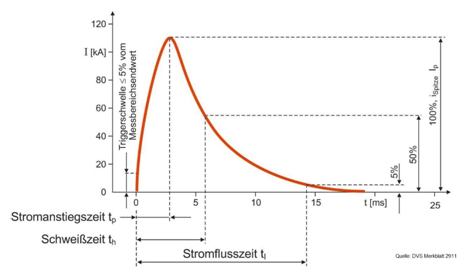
Capacitor discharge welding has been used since the mid 50s for selected welding tasks, due to the short current increase time and the comparatively low and rapid heat input in comparison to conventional spot or projection welding.

Capacitor discharge welding is generally known in the abbreviated form as CD welding or capacitor pulse welding. Capacitor discharge welding belongs to the group of conductive resistance pressure welding processes. It applies as a possible current source for projection welding, although it is also applied as resistance spot welding. Today, it is projection welding that dominates. The process is characterised by one joining partner exhibiting a hump-like contour so that the current flow is concentrated on the contact surface. With resistance spot welding, the necessary current concentration is realised through the geometry of the electrode tip. Whilst resistance spot welding is increasingly employed in body shell construction or when connecting thin sheet parts, capacitor discharge welding is used in diverse applications for example in gear manufacturing or when joining weld nuts and bolts with different material and wall thickness combinations, in order to save weight, energy and resources.

Within conductive resistance pressure welding processes, differentiation is made between capacitor discharge welding and other processes due to the type of welding current source and the associated current form. In contrast to conventional alternating current or direct current sources, work does not take place with multiple current pulses that are taken directly from the mains supply network and lead to an asymmetrical network load, but rather just with a single, short and high current pulse (up to 1000 kA), which is supplied via a transformed capacitor discharge. The welding time with capacitor discharge welding is usually less than 20 ms, whereby significantly shorter welding times are also possible.

To date, it was assumed with CD welding that the progression of the welding current is largely determined by the design characteristics of the machine (the capacitance of the capacitors, the translation ratio of the transformer and the inductance of the welding current circuit). Variation of the welding parameters is only possible to a limited degree via the charging voltage of the capacitors. The tightly restricted limits can be expanded with the combined pulse technology (CP) system.

With four connected in parallel, it is possible to specifically influence the course of the welding current. This system technology now enables process control tailored to the joining task. For example, a capacitance change can take place without mechanical reconnection, or peak currents increased or reduced. Furthermore, it is possible to simulate the progressions of the welding currents using software connected with the welding system.

Video: Multi pulse welding of a weld nut

The advantages of CD welding pertain to three areas:


1. Materials:

  • Welding mixed connections → copper or brass with steel
  • Welding steels with a C-content of over 0.2% → gearbox components
  • Welding sintered materials → Diamond/bronze mixtures for masonry drills and saw blades
  • Welding hardened materials → Machine elements
  • Welding high-strength materials → Components for the automotive industry (A-pillar, B-pillar, etc.)

2. Surfaces:

  • Welding galvanic and hot-dip galvanised surfaces without destroying the zinc coating
  • Welding chromated surfaces
  • Welding chrome/nickel steels with thin sheet thicknesses without producing undesired annealing colours
  • Welding single-sided non-conductive coated sheets

3. Geometry:

  • Welding extremely varying wall thicknesses and sheet thicknesses → membranes on solid bodies
  • Seal welding circular projections up to a diameter of 200 mm
  • Multiple projection welding → 50 projections in a single weld