

Aspects of the power system and the re-setting unit are not considered here.
The electrical system of a capacitor discharge machine (CD machine) influences the welding behaviour. Whilst the operator is only able to affect the welding process via the charging voltage of the capacitors, and therefore via the energy fed to the joining process, it is ultimately the resistance and inductance of the machine, as well as the capacitance of the capacitor bank – the basic variables – that determine the current progression. Whilst the capacitance is installed in the machine as a compact module, the overall resistance and inductance comprise multiple main components. As the following figure shows, the transformer variables and the inductance of the secondary circuit have the greatest influence.
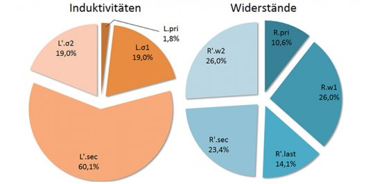
Shares of the assemblies in the overall inductance and resistance of a CD machine with: L.o1, L‘.o2 as leakage inductances and R.w1, R‘.w2 as winding resistances of the transformer; R.pri, L.pri as variables of the primary circuit and R‘.sec, L‘.sec of the secondary circuit and R‘.last the load resistance.
According to a widely-held opinion, welding parameters cannot be transferred from one CD machine to another. This drawback arises due to the unknown basic variables of the machines and heavily simplified designated welding parameters, which are limited almost exclusively to the specification of energy E and peak current IP. According to this, the two curves in the following figure show identical parameters with E = 8.45 kWs and IP = 105 kA, although they depict strongly deviating welding behaviour.
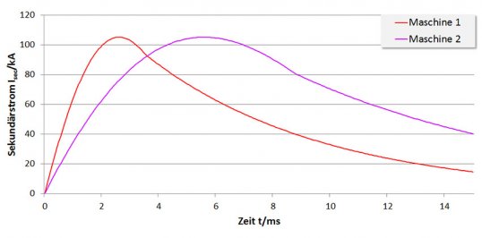
Current characteristic curves of two machines with different basic variables but identical welding parameters.
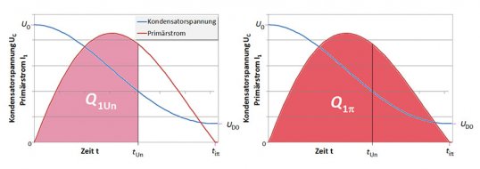
Kapkon brings this work status with CD machines as the “unknown entity” to an end. A process has been developed, with which the basic variables of an arbitrary machine can be determined through measurements. For checking purposes, the CD machine is operated without the freewheeling branch with different charging voltages in short circuit and additionally with a defined load resistance. The test series must be executed for each capacitor of a machine and for each translation ratio of the transformer. The measurements determine the current flow duration tiπ, the initial charging voltage U0 and back charging voltage UD0 as well as the current-time integrals over the discharge time tUn of the capacitor Q1Un and over the current flow duration Q1πn of the primary current.
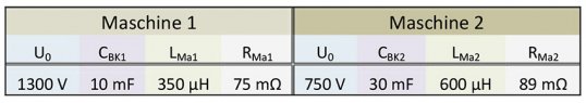
On this basis it is possible to calculate the basic variables, which – for the two machines with the current characteristic curves shown in the figure above – are as follows:
The different basic variables deliver the electro-technical explanation for the current progressions. However, it is hardly possible to derive welding characteristics here. These can be recognised significantly more clearly if the key parameters are juxtaposed:
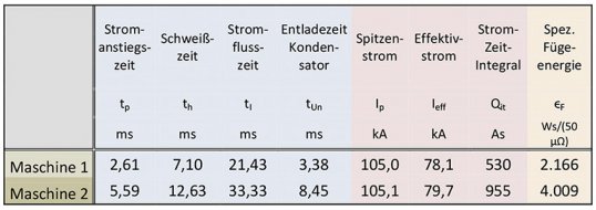
In this way, the differences in the welding behaviour of the two machines are clear. However, the commonalities such as the peak current and supplied energy are shown. From 2018, Kapkon will be supplying all machines with an ID that provides information on the electrical data. However, machines that have already been supplied (including external brands) can also be retrospectively measured; Kapkon offers a service in this regard. Through cyclical testing, it is possible to monitor the condition of a machine and detect ageing and wear in this way.